Understanding AC-6b
When switching capacitors, contactors are essential, especially in industrial settings where power factor adjustment is crucial. According to IEC 60947-4-1’s AC-6b Utilization Category, capacitors are frequently used in low-voltage installations to improve power factor and rectify reactive energy. However, during capacitor energization, significant transient conditions arise, characterized by high-amplitude and high-frequency overcurrents.
Two Types of Power Factor Correction
The magnitude of these inrush current peaks is influenced by factors such as network inductances, transformer power, short-circuit voltage, and the type of power factor correction utilized. There are two primary methods of power factor correction:
Fixed
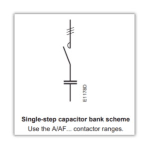
Involves a single-step energization of a capacitor bank by a contactor, resulting in inrush current peaks potentially reaching 30 times the nominal current of the capacitor bank.
Automatic
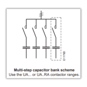
Involves multiple steps of capacitor banks, with inrush current peaks reaching up to 100 times the nominal current of the step being energized.
Steady-State Condition Information
Harmonics and voltage tolerances lead to a permanent circulating current estimated at 1.3 times the nominal current of the capacitor. To ensure reliable operation, contactors must be designed to withstand this permanent current, which can reach 1.5 times the nominal current of the capacitor bank, as well as the short but high peak currents upon pole closing.
Capacitor Bank Switching Versions
UA..RA Contactors
Incorporates damping resistors to mitigate the highest inrush currents, protecting both the contactor and capacitor.
UA… Contactors
Designed for applications where the maximum permissible peak current is less than 100 times the nominal rms current of the switched capacitor.
A… and AF… Standard Contactors
Suitable for scenarios where the maximum permissible peak current is less than 30 times the nominal rms current of the switched capacitor.
Knowing these differences allows you to make informed decisions concerning your electrical systems. stay informed!